|
|
|
In this project we implemented a real-time physical simulator on cloth using basic idea of masses and springes. We build data structures that discretely represent the cloth, apply several constraits to the cloth, add some clever tricks to make cloth more realistic, and apply numerical integration eventually to simulate how the cloth moves over time. We also added collision of the cloth with sphere, plane, and also itself to represent scenerios with more than one cloth objects. Finally, during the last part we revisit previous ray tracing ideas for proj3-1 and proj3-2, and apply a much more efficient shader program to generate real-time ray tracing simulation. Although overall simulation is still relatively simple, it is cool to see how GPU can significantly speed up the process of ray tracing using parallel computing. It is cool to implement those shaders that are also fundamental to modern day PC games that present highly complex 3D scenes in real time.
In this part we build a grid of masses and springs. We create two vectors point_masses and springs to discretely represent the cloth. We create num_width_points * num_height_points of point masses, with increment (width / (num_width_points-1)) on the row axis and (height / (num_height_points-1)) on the column axis. We assign different xyz values based on whether the cloth's orientation is horizontal or vertical. If it is vertical, we define a small random offset using (rand()) / RAND_MAX * 0.002 - 0.001 for the z coordinate. We store the point_masses in a row-major order. After initiating all the point_masses, we loop through each of them to tag whether they are pinned or not.
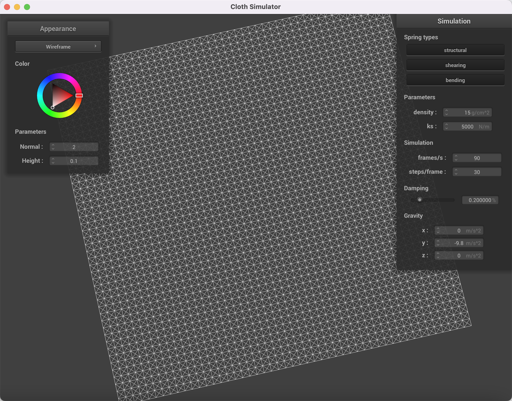
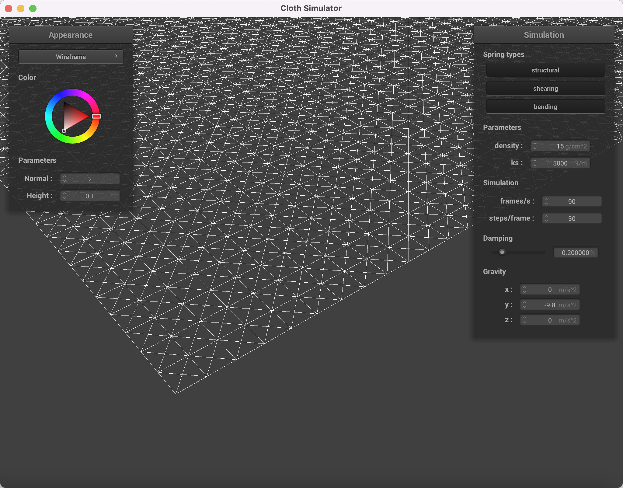
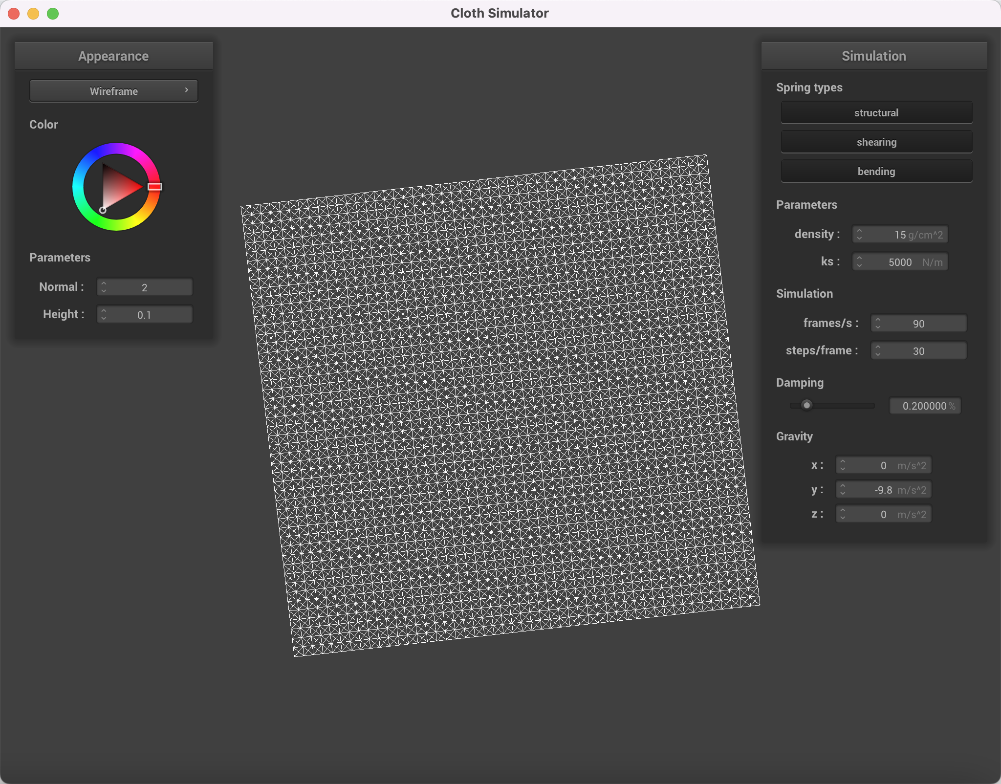
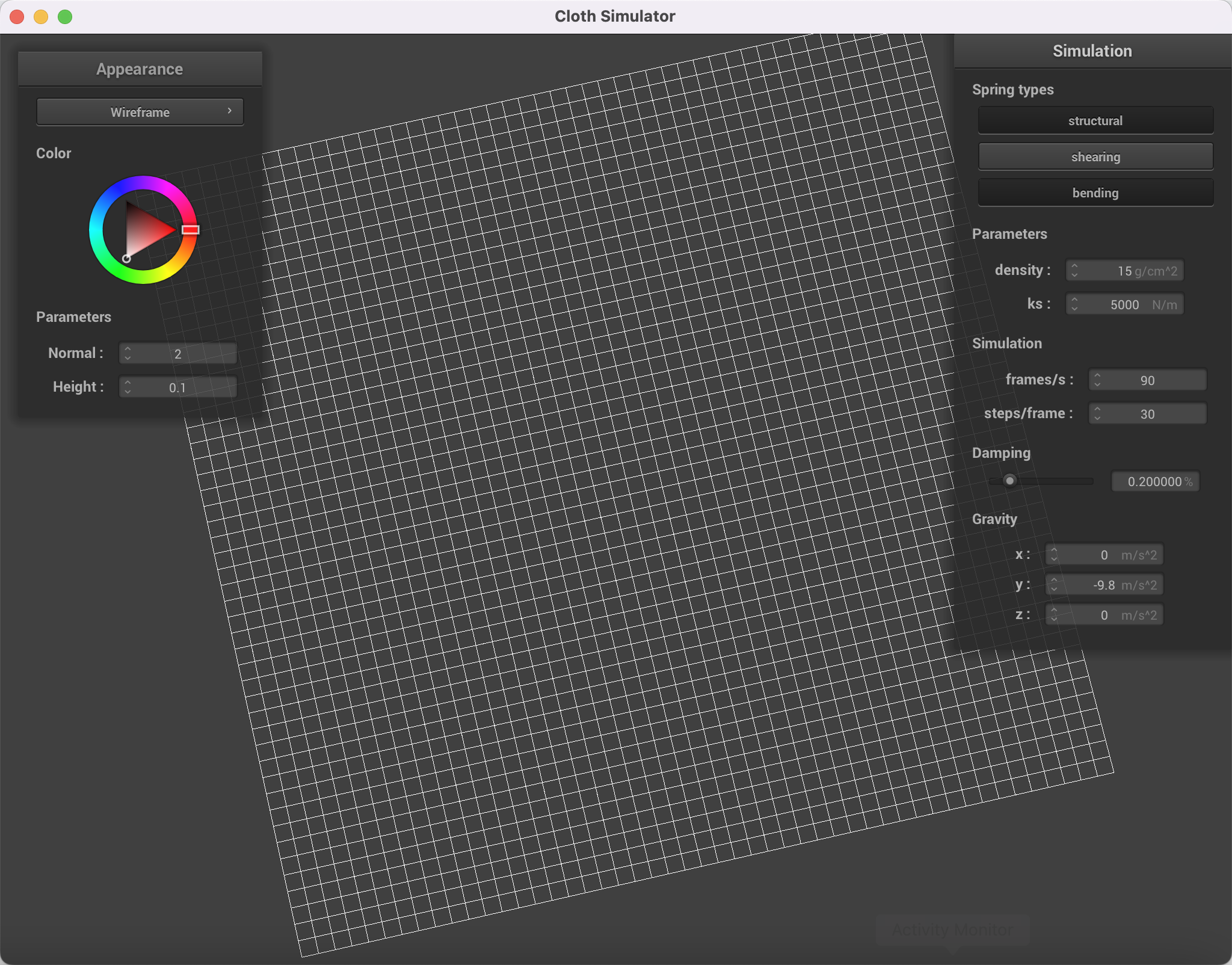
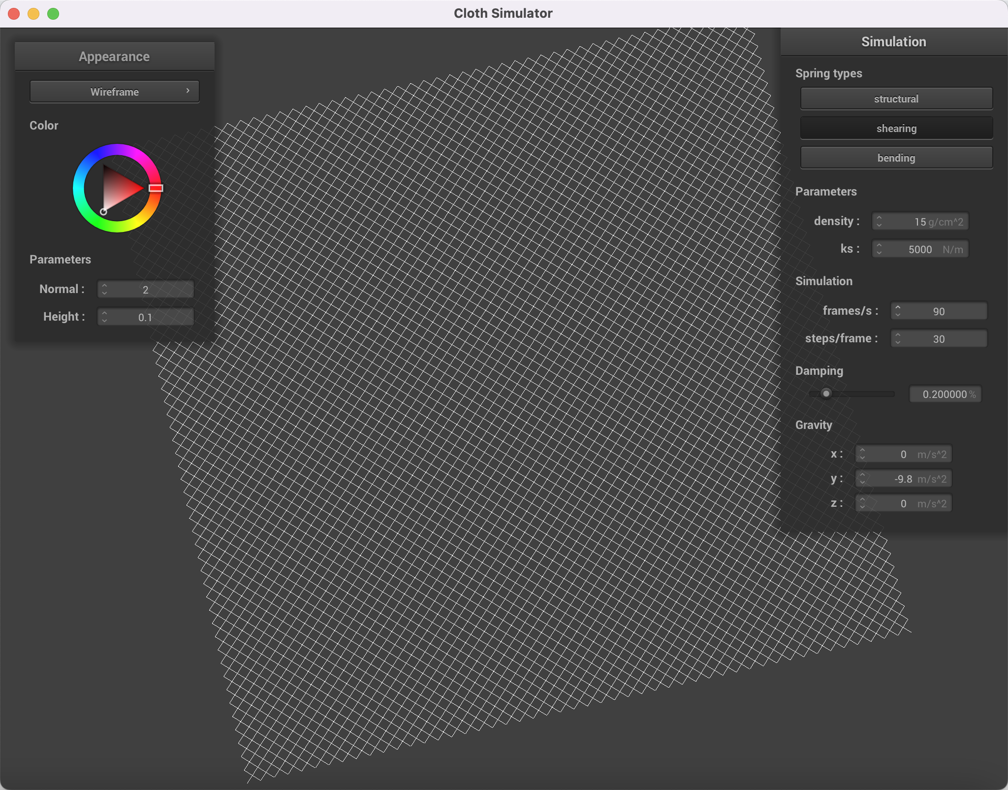
After the point_masses are created, we add springs between point_masses to constrain them. There are 3 types of constraits, structural, shearing, and bending. We loop through point_masses three times to add those three constraits. Edges need to be considered separately, such as the first column does not have a structural constraits to its left. The final implementation should be able to show a multiple squares with crosses inside when all three constraits are applied.
Take some screenshots of scene/pinned2.json from a viewing angle where you can clearly see the cloth wireframe to show the structure of your point masses and springs.
|
|
|
|
Show us what the wireframe looks like (1) without any shearing constraints, (2) with only shearing constraints, and (3) with all constraints.
|
|
|
|
In part 2 we integrate the physical equations of motion into the system of masses and springs to simulate how they move from one time step to the next. We loop through each point mass pm. Before integrating all forces, we first make sure that pm->force is initiate as 0. Then, we first loop through each external acceleration and apply F=ma to this pm's force. Second, we apply the spring connection forces. We check two things, 1) whether the specific constrait is enabled by the ClothedParameter cp; 2) whether this spring's type matches the constrait we are currently looking at. If conditions are met, we compute the force applied to the two point mass using Hooke's law, and considers the direction of the force by ±(positionA - positionB).unit().
After getting all the forces on each point mass, we loop through each point mass again to use Verlet integration to compute new point mass positions. In Verlet integration velocity times delta_t is approximated by (current_position - last_position). We also add a damping term to velocity to account for loss of energy due to friction etc. For pinned points, we do not change their position at all.
Finally, we add a smart trick from SIGGRAPH 1995 Provot paper. For each spring, we apply this constraint by correcting the two point masses' positions such that the spring's length is at most 10% greater than its rest_length at the end of any time step. We make sure that we only change the distance between two point masses not the direction by using the magnitude of the difference times the correct direction ±(pA-pB).unit(). If both are not pinned, we apply half of the correction to each point mass. If one is pinned, apply full correction to the other. If both are pinned, do nothing (they are also not moving apart any way).
Experiment with some the parameters in the simulation. To do so, pause the simulation at the start with P, modify the values of interest, and then resume by pressing P again. You can also restart the simulation at any time from the cloth's starting position by pressing R.
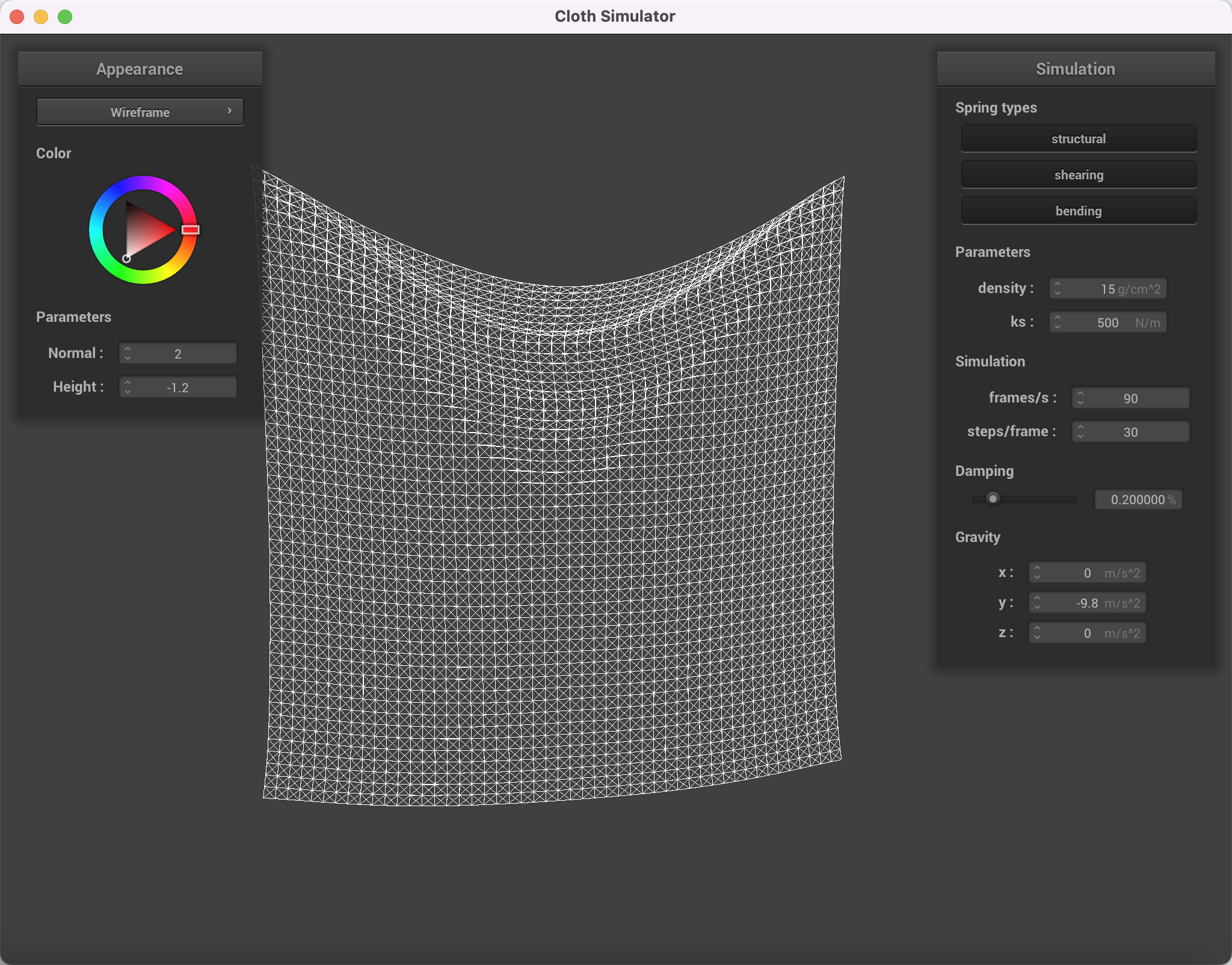
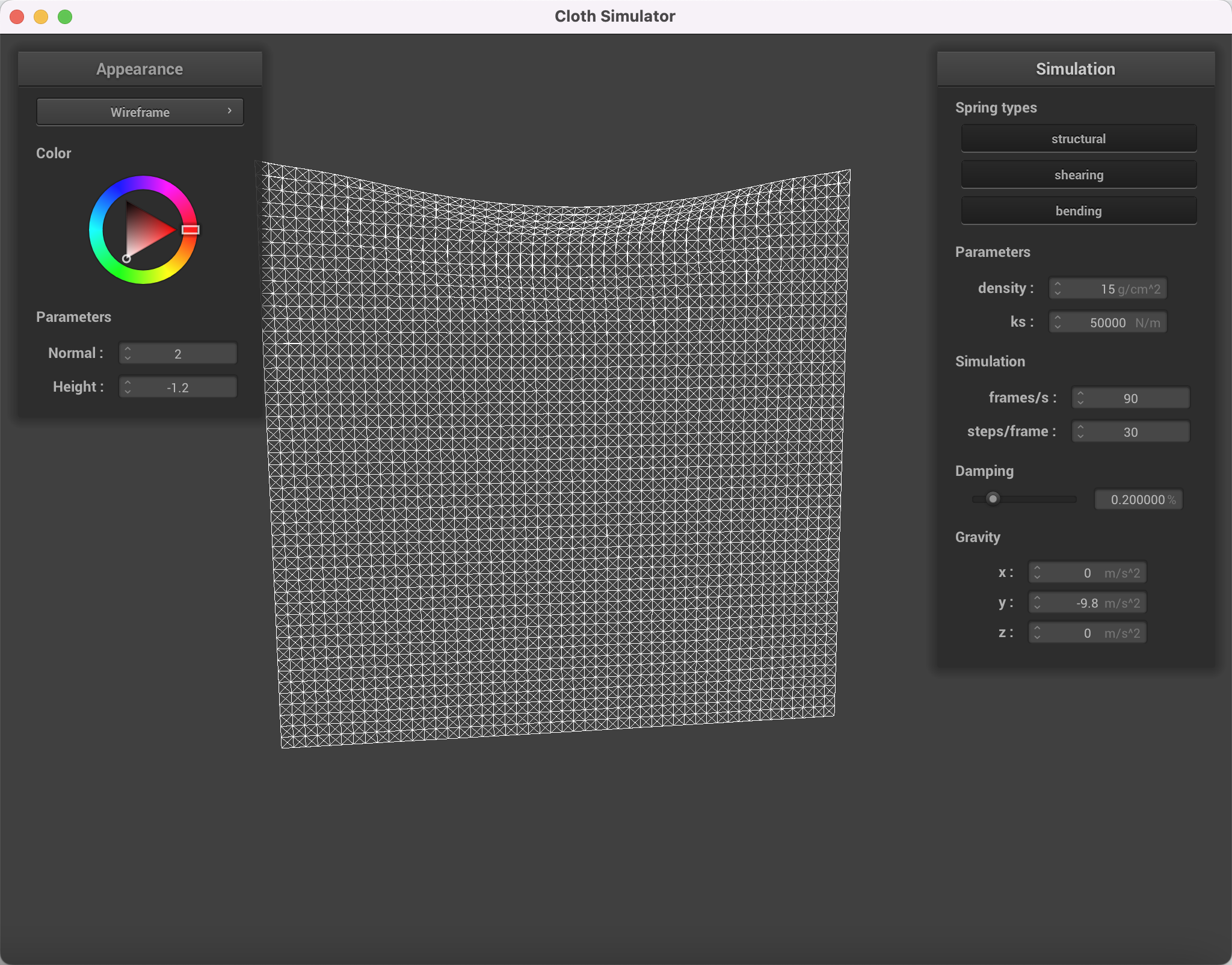
Describe the effects of changing the spring constantks; how does the cloth behave from start to rest with a very lowks? A highks?
|
|
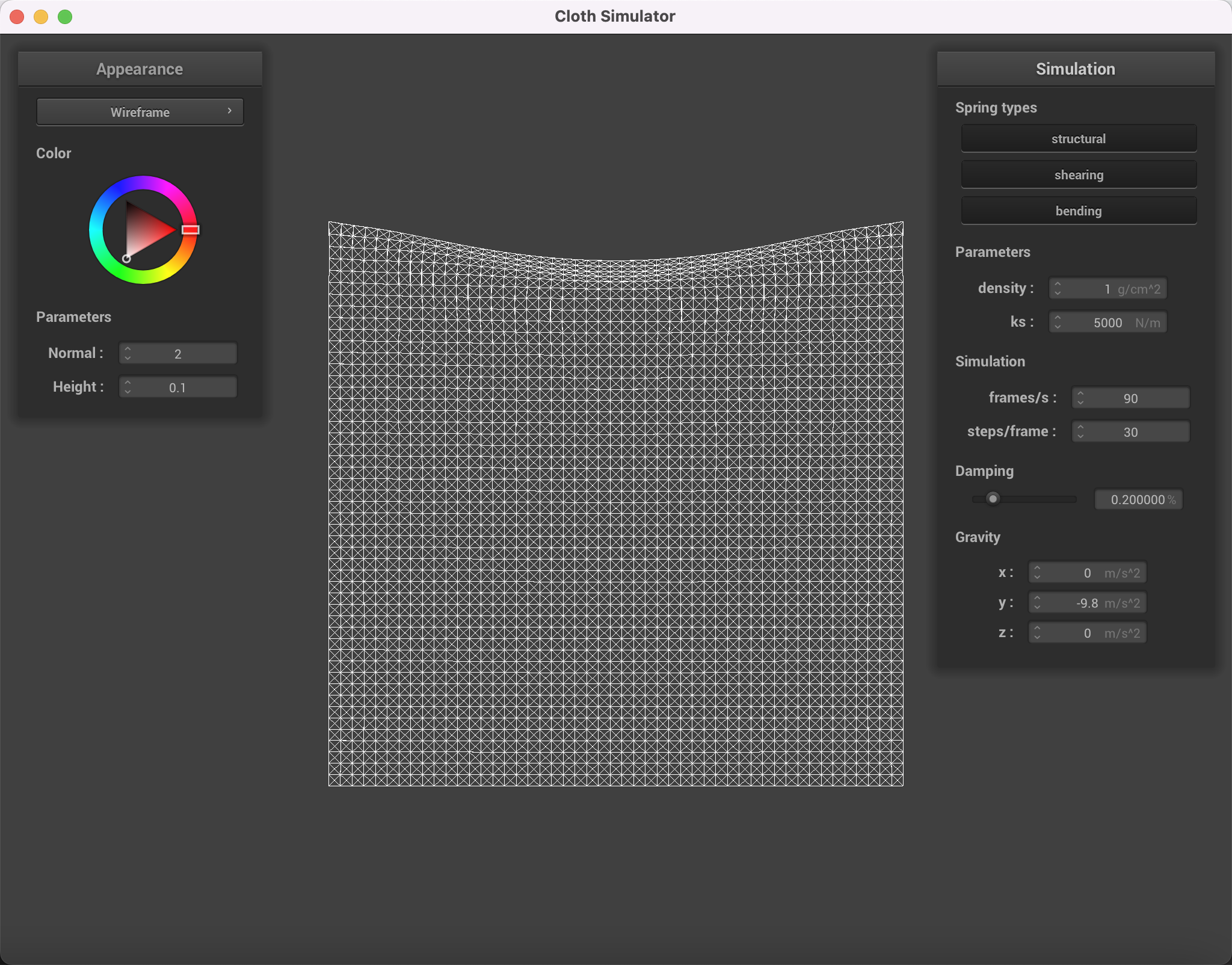
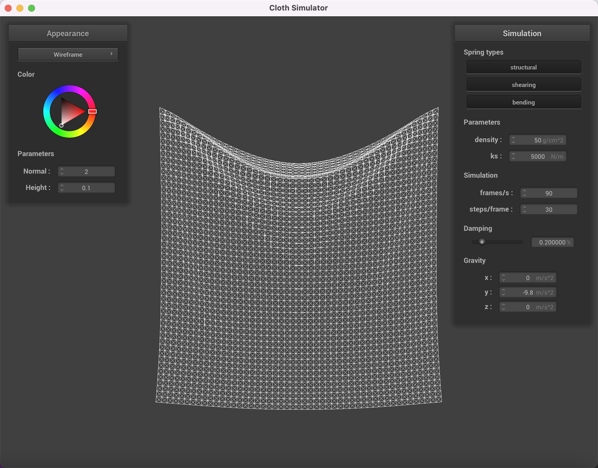
What about for density?
|
|
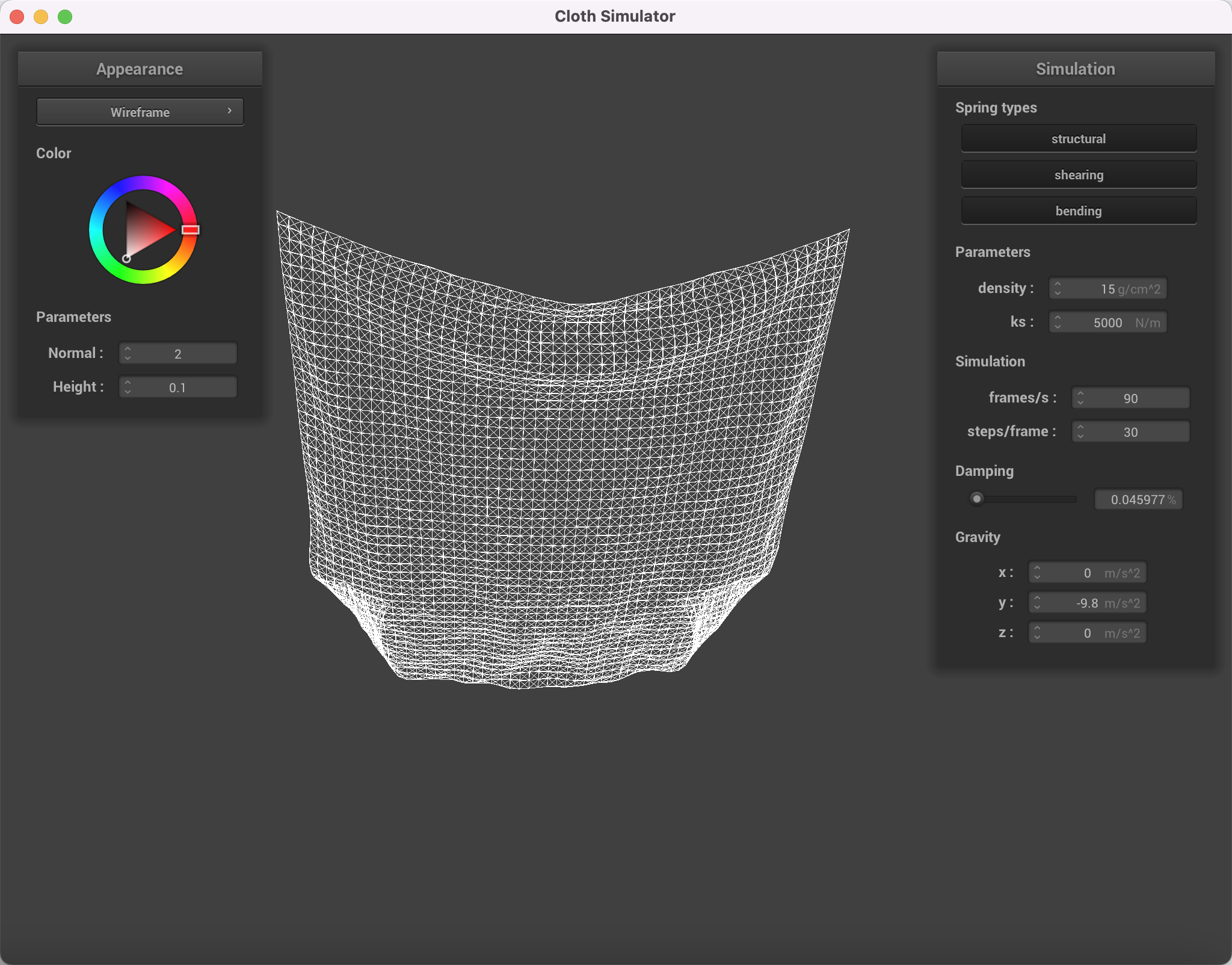
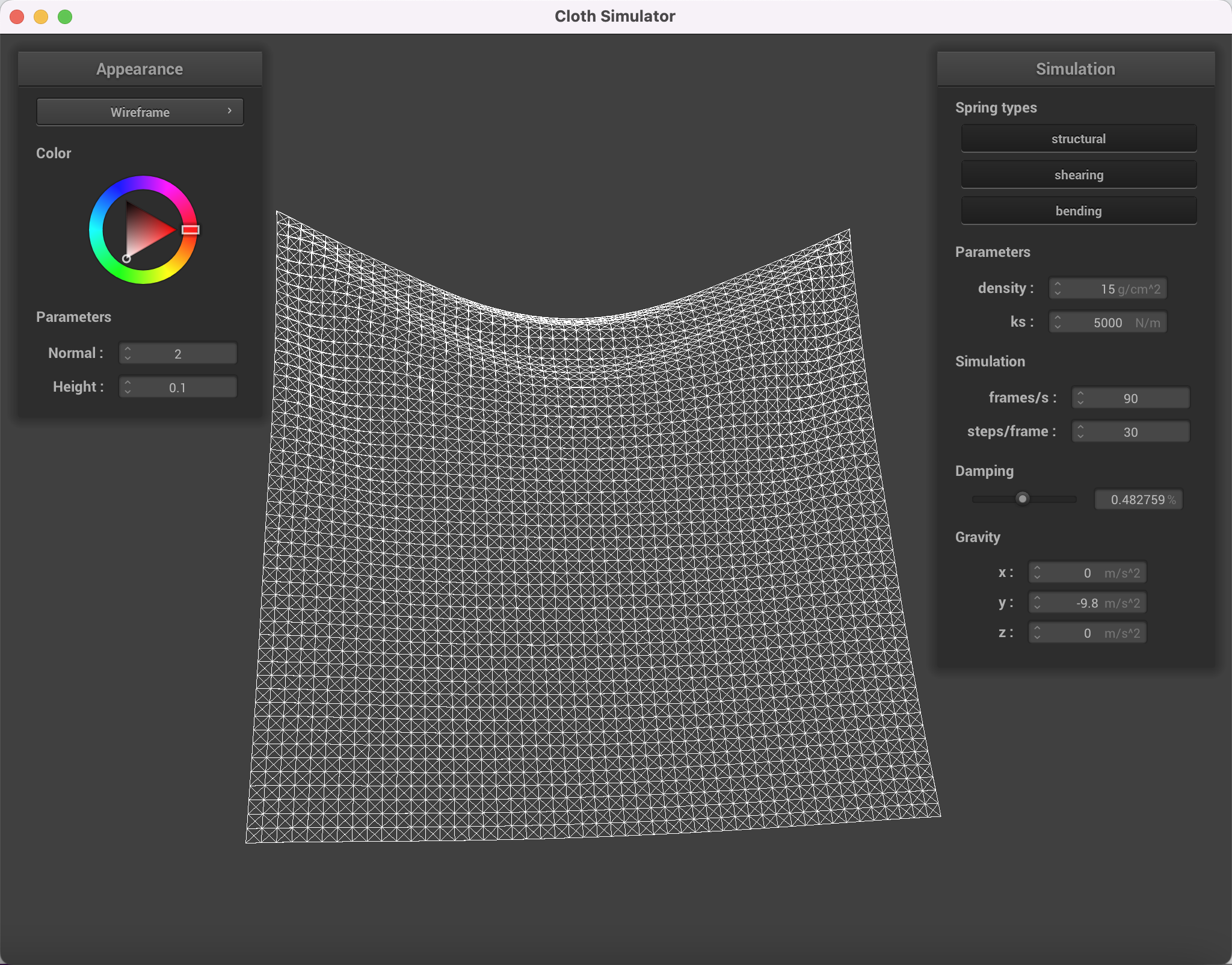
What about for damping?
|
|
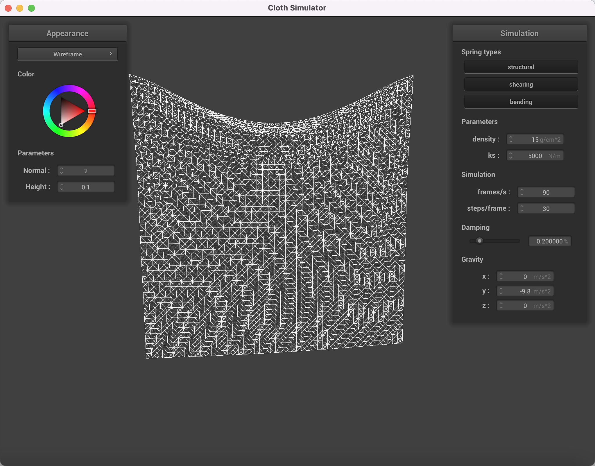
For each of the above, observe any noticeable differences in the cloth compared to the default parameters and show us some screenshots of those interesting differences and describe when they occur.
Small damping causes the cloth to retain more energy and speed when reaching the bottom. Thus, the cloth even swings to the other side instead of stopping at steady state.
|
|
Small ks makes the spring less stiff (the force between each point mass now is smaller). Thus, the cloth is looser with a smaller ks compared to default, making the middle part of the cloth bend down more when reaches balance with gravity.
|
|
|
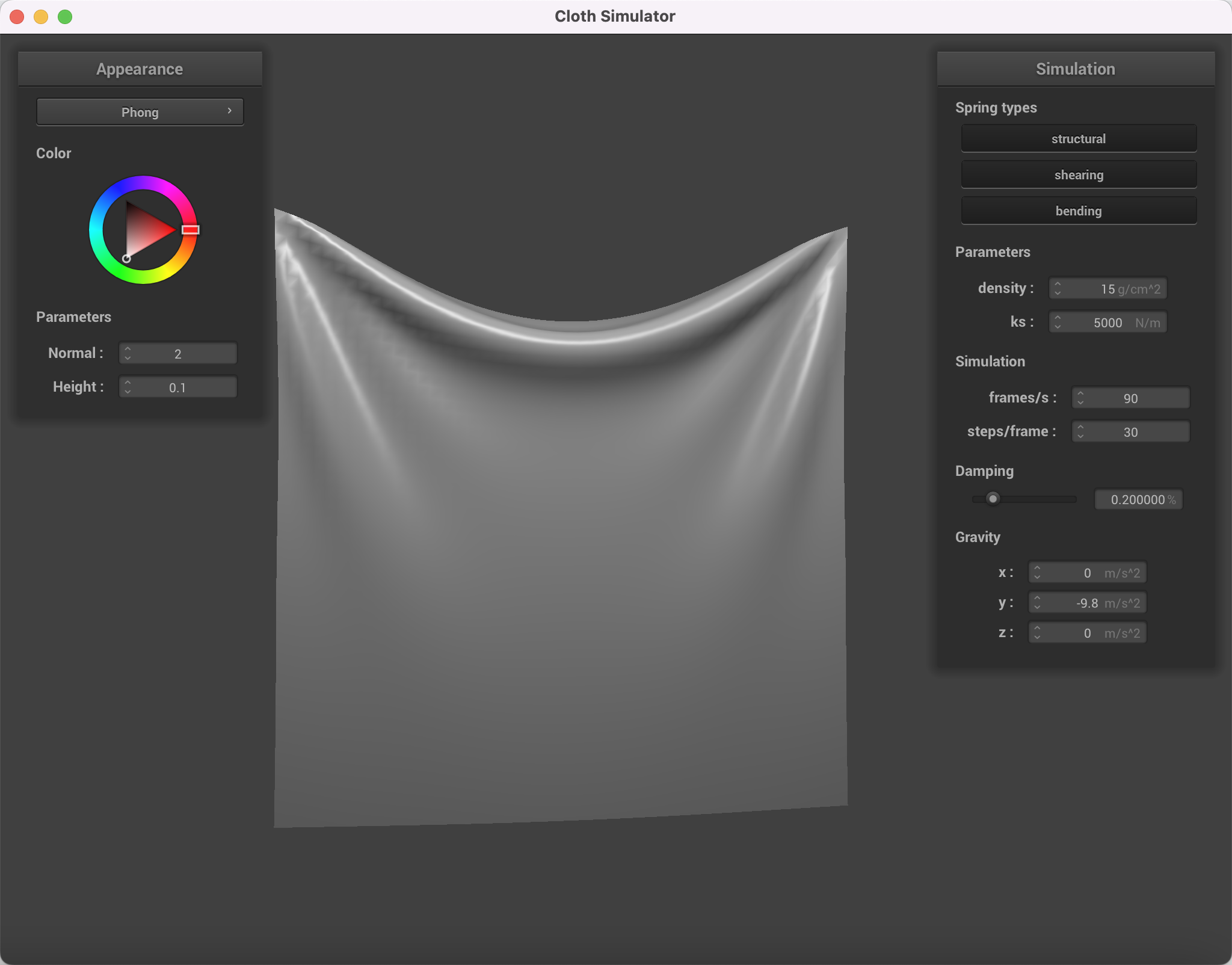
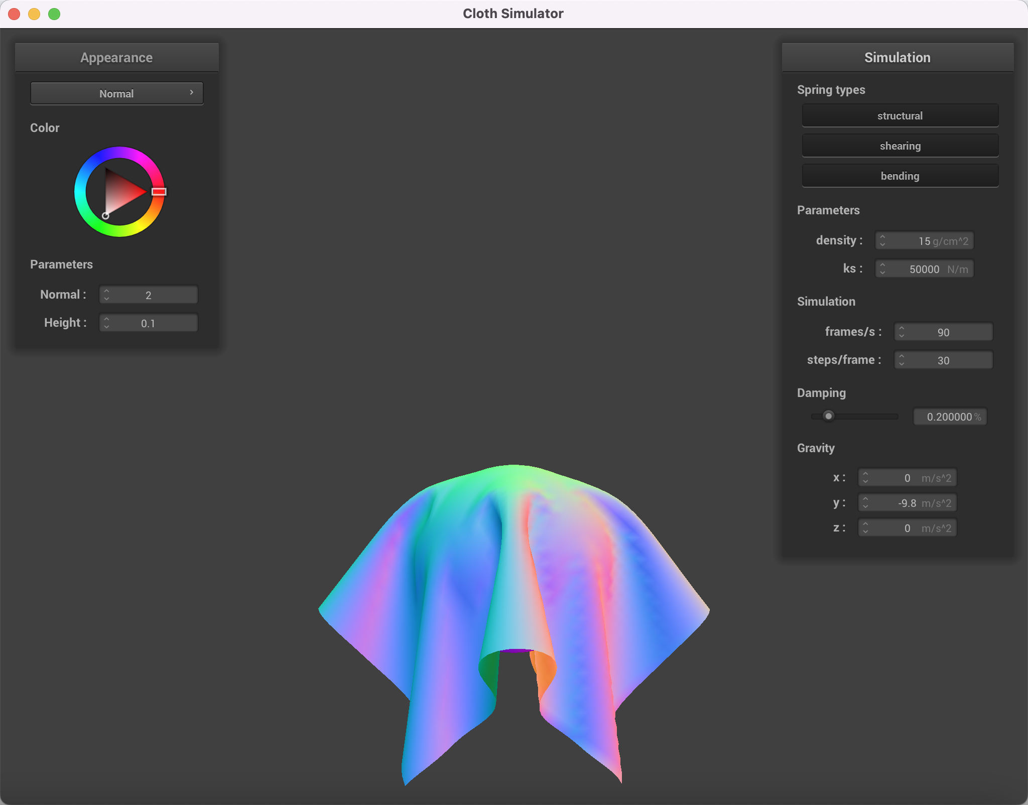
Show us a screenshot of your shaded cloth from scene/pinned4.json in its final resting state! If you choose to use different parameters than the default ones, please list them.
|
|
In Part3, we implement collision handling for the cloth with a sphere and a plane. The idea is simple, for each collision object in collision_objects, we check that for each point mass in point_masses, whether the point mass's position lies inside the primitive of the object. If this is true, we adjust the point mass's position so that it stays just outside the primitive's surface, accounting for friction as we do so.
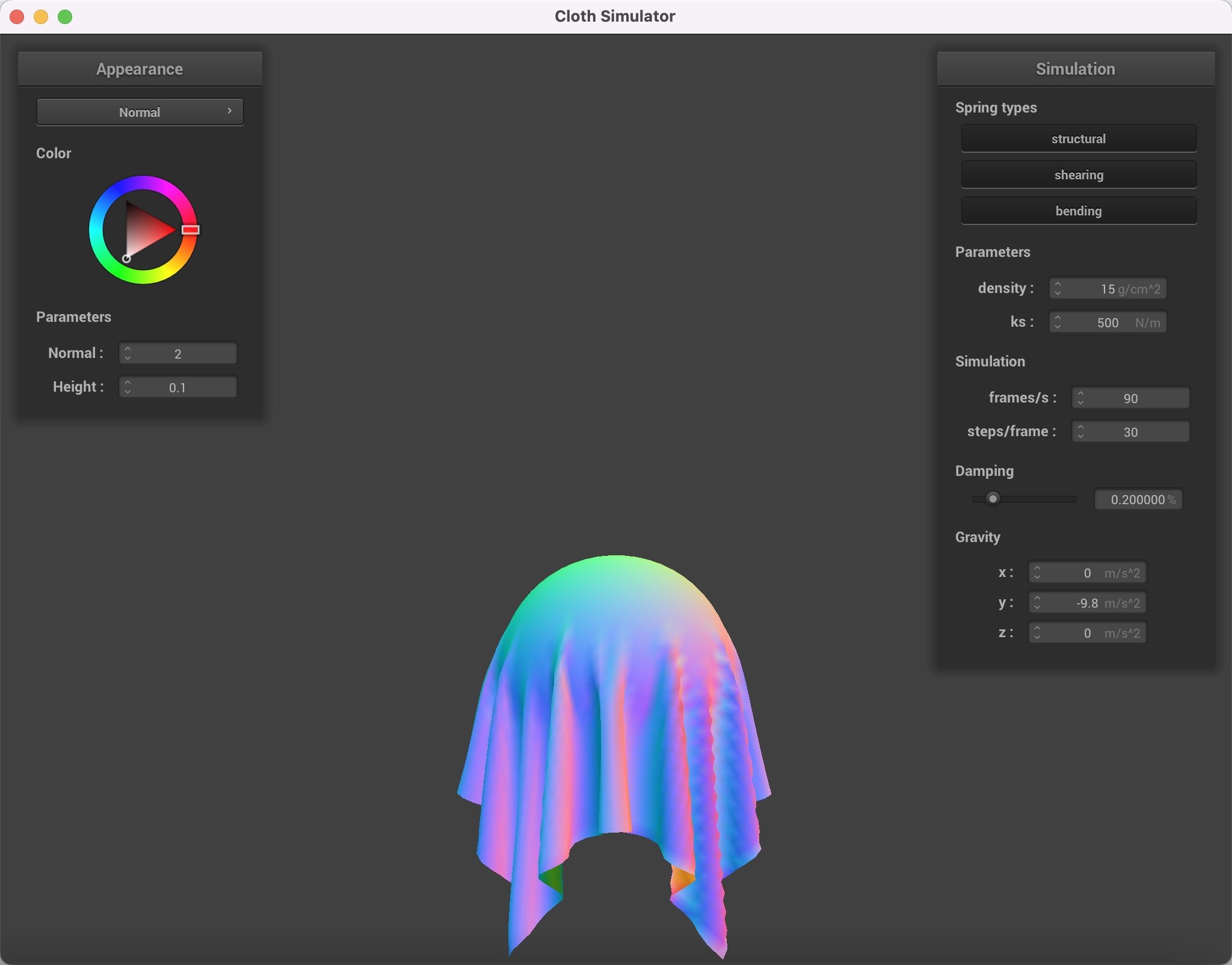
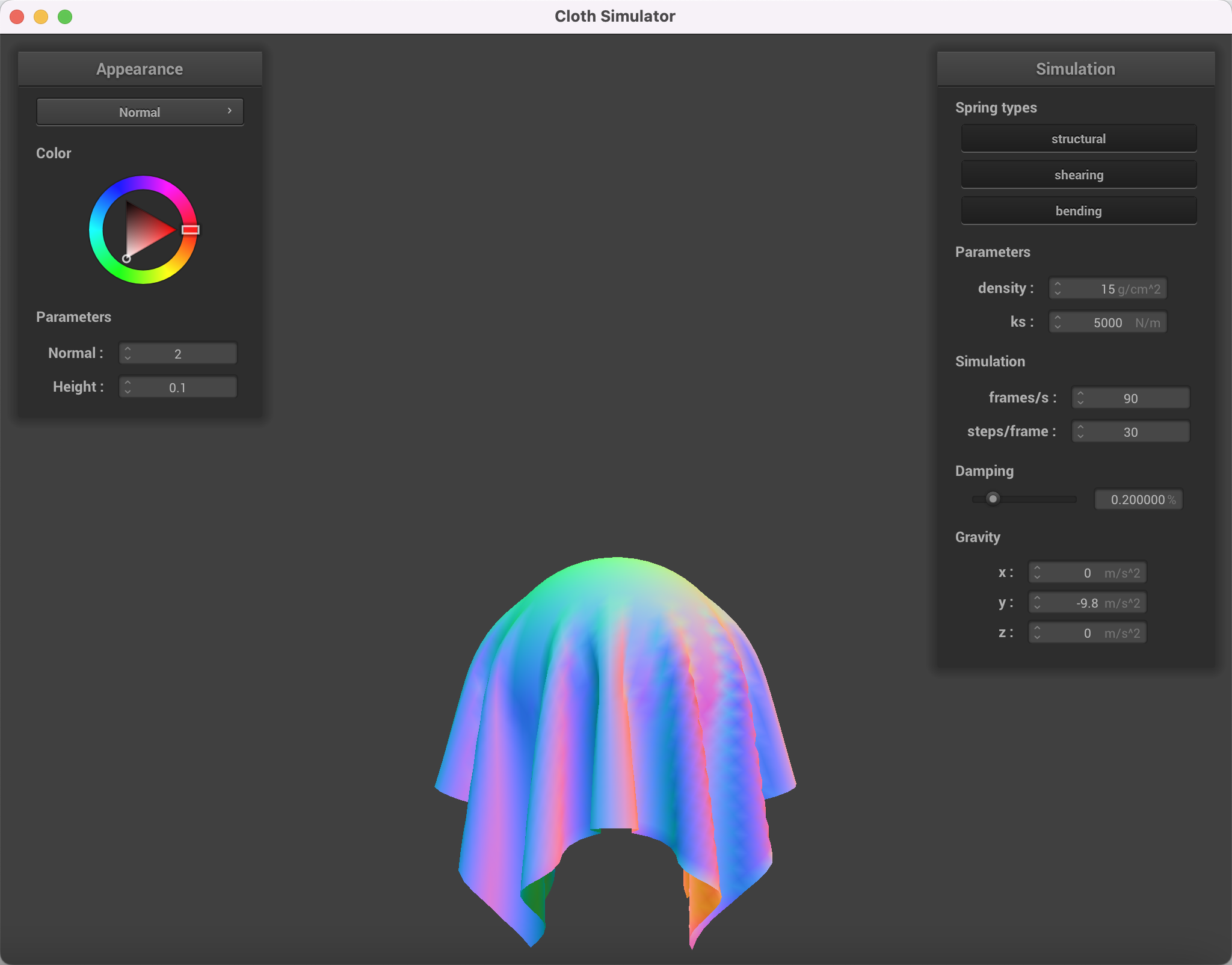
Show us screenshots of your shaded cloth from scene/sphere.json in its final resting state on the sphere using the defaultks = 5000as well as withks = 500andks = 50000.
The larger the ks, the more stiff the cloth is. Smaller ks makes the cloth extends longer when resting on the sphere and fiting the sphere shape better. ks represents the stiffness of the cloth (spring), which a larger ks makes the cloth mateiral look more stiff and less flexible when covering a shape.
|
|
|
Show us a screenshot of your shaded cloth lying peacefully at rest on the plane. If you haven't by now, feel free to express your colorful creativity with the cloth! (You will need to complete the shaders portion first to show custom colors.)
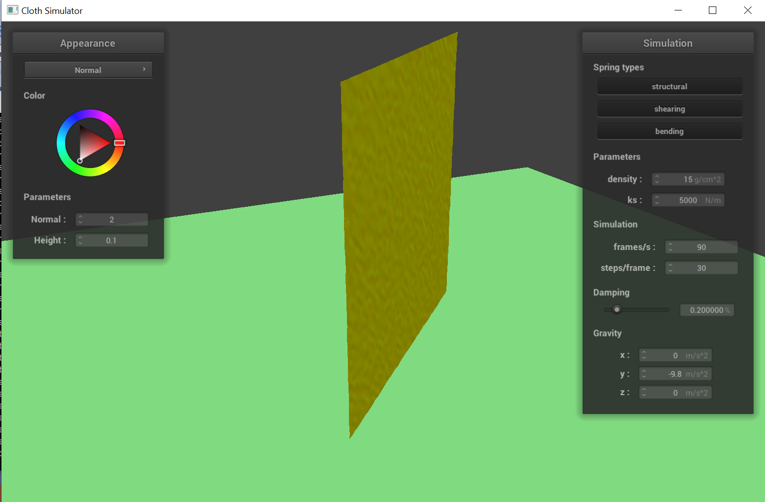
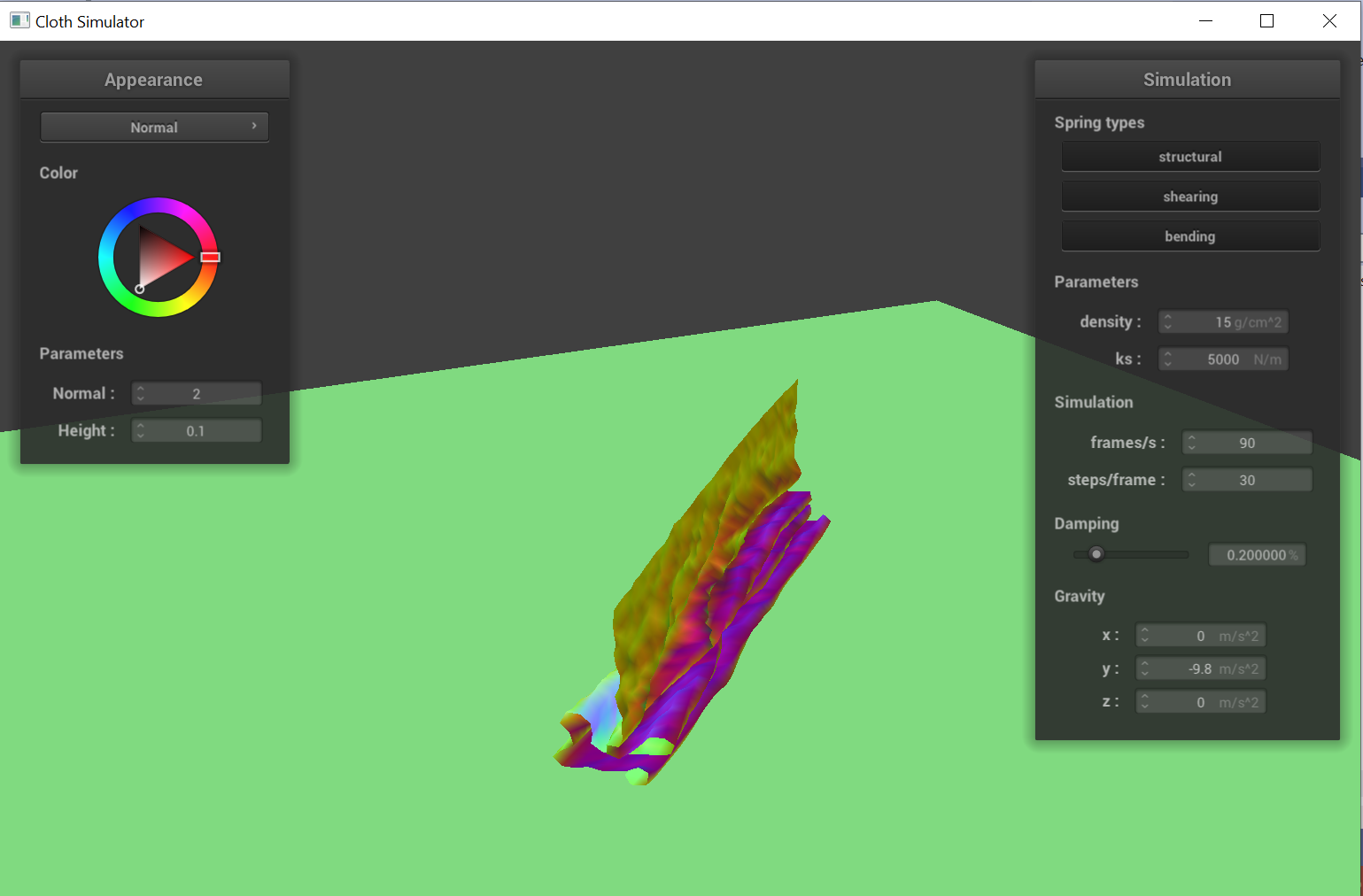
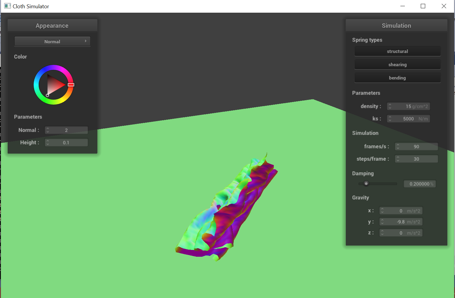
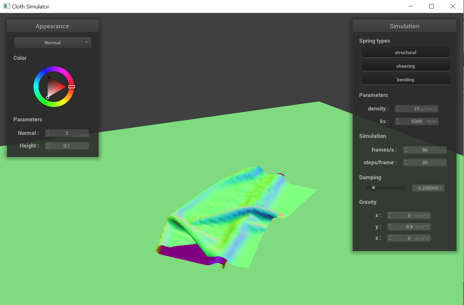
Show us at least 3 screenshots that document how your cloth falls and folds on itself, starting with an early, initial self-collision and ending with the cloth at a more restful state (even if it is still slightly bouncy on the ground).
|
|
|
|
To handle self collision at each time step t, we use a hash table to store the position of each pointmass to speed up
the calculations, which would be O(n^2) with naive for-loop implementation. Specifically, we first calculate the 3d-box with
dimensions w * h * t where w = 3 * width / num_width_points, h = 3 * height / num_height_points, and
t = max(w, h) that the point mass belongs to. The hash function we used is: hash = x*2^14 + y*2^7 + z.
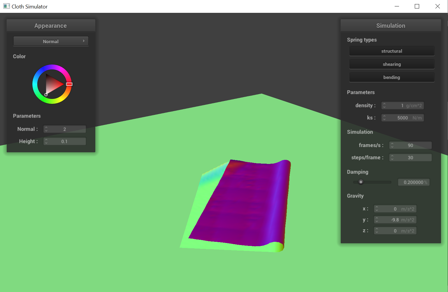
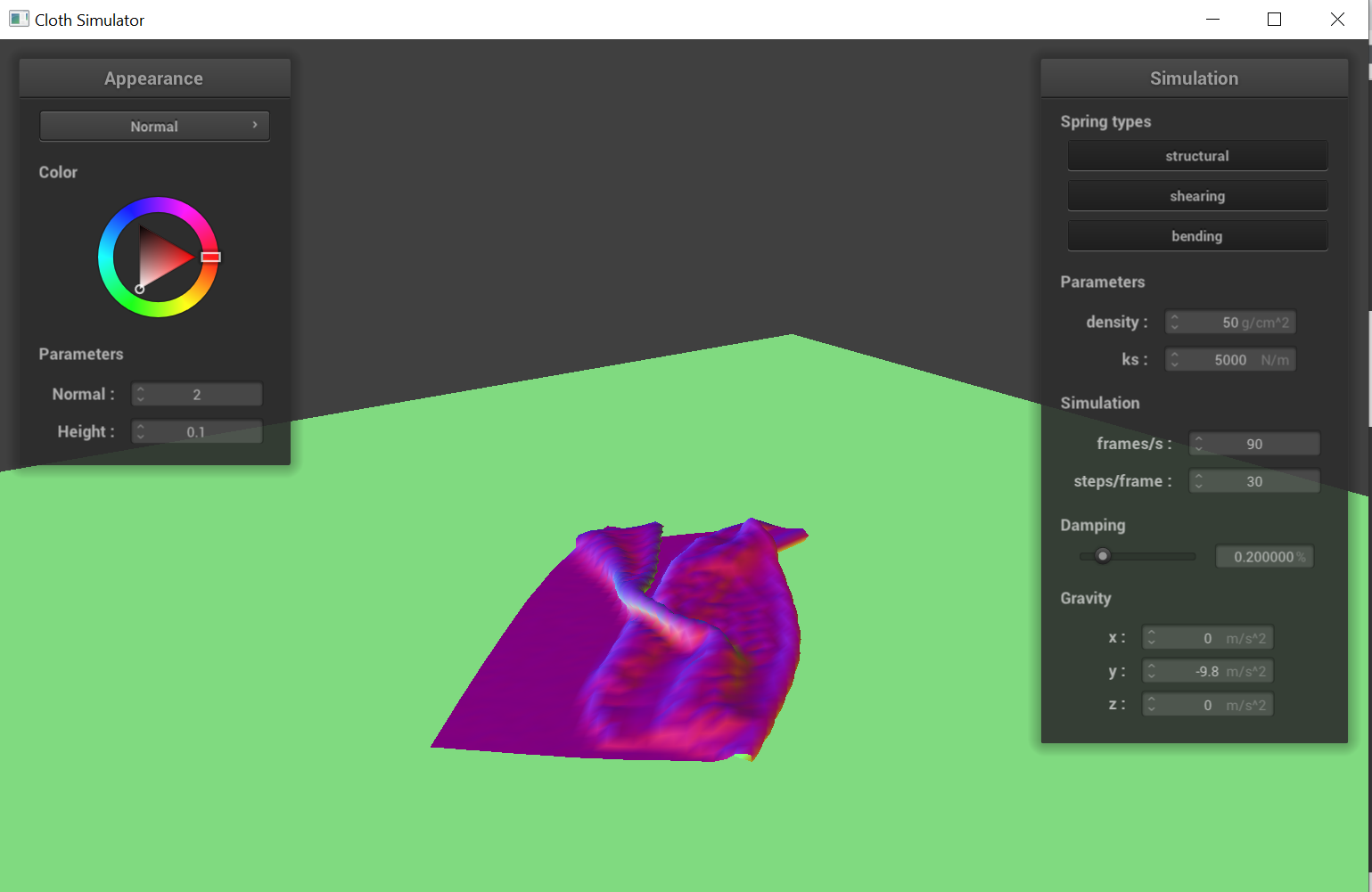
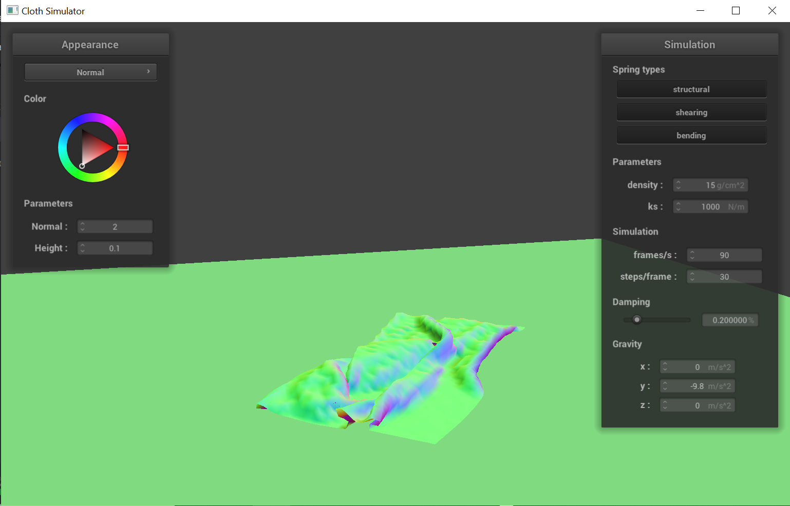
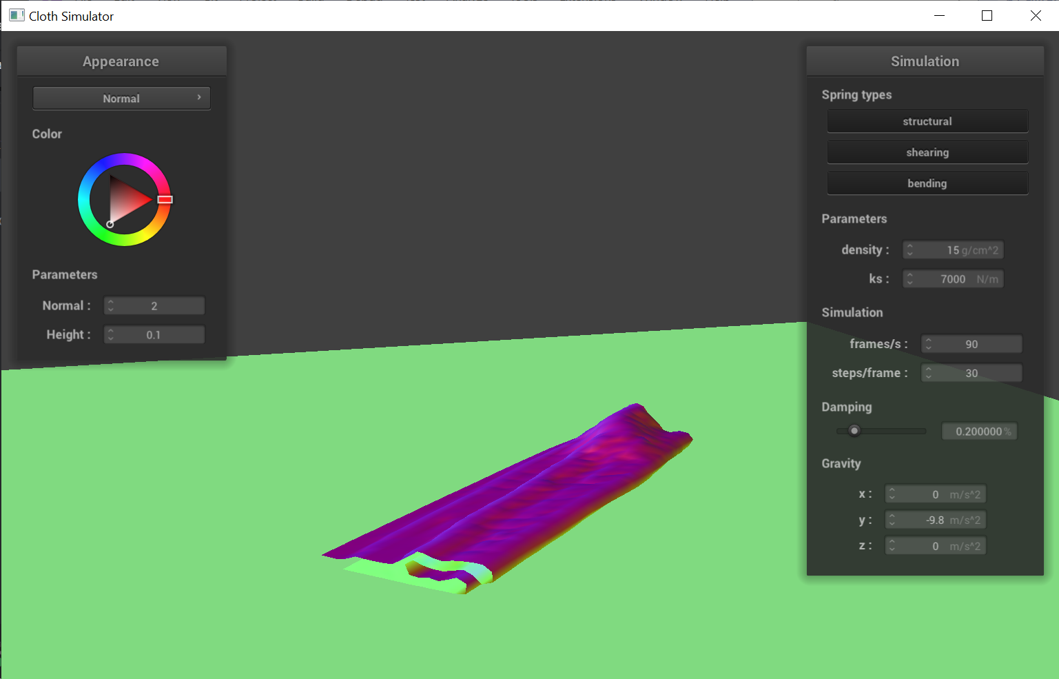
Vary thedensityas well asksand describe with words and screenshots how they affect the behavior of the cloth as it falls on itself.
|
|
|
|
Tweaking around the density and ks parameters, we found out that both decreasing density
and increasing spring constant (ks) will result in smoother fabrics as it settles. This makes sense, because the point masses
are under two types of forces - external gravitational force and spring forces. Since spring forces are what flattens the
fabric out, any change to parameters that strengthens the springs (i.e. increasing ks) or weakens external forces
(i.e. decreasing density which decreases mass of pm) will result in positions with smoother surfaces. \n
In addition, there are other differences that we observed: lower spring forces (relative to gravitational forces) will
result in flat surfaces to be more "bumpy", folds to be rounder, and more ridges (i.e. verticle folds).
Explain in your own words what is a shader program and how vertex and fragment shaders work together to create lighting and material effects.
GLSL shader programs are isolated programs that can run on GPU cores to perform tasks in the rendering pipeline. Compared to computations done on the CPU, running on GPU results in faster rendering as it enables better parralellization. For our project, we worked with two types of shaders: vertex shaders and fragment shaders. Vertex shaders perform transformations to the individual virdices, like calculating its global position and normal vectors. The outputs from the vertex shaders can then be used as inputs for fragment shaders, which perform coloring tasks after rasterization.
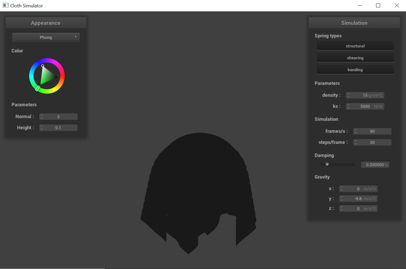
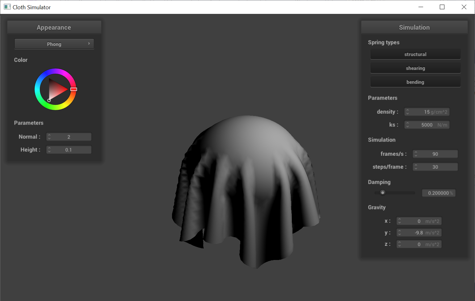
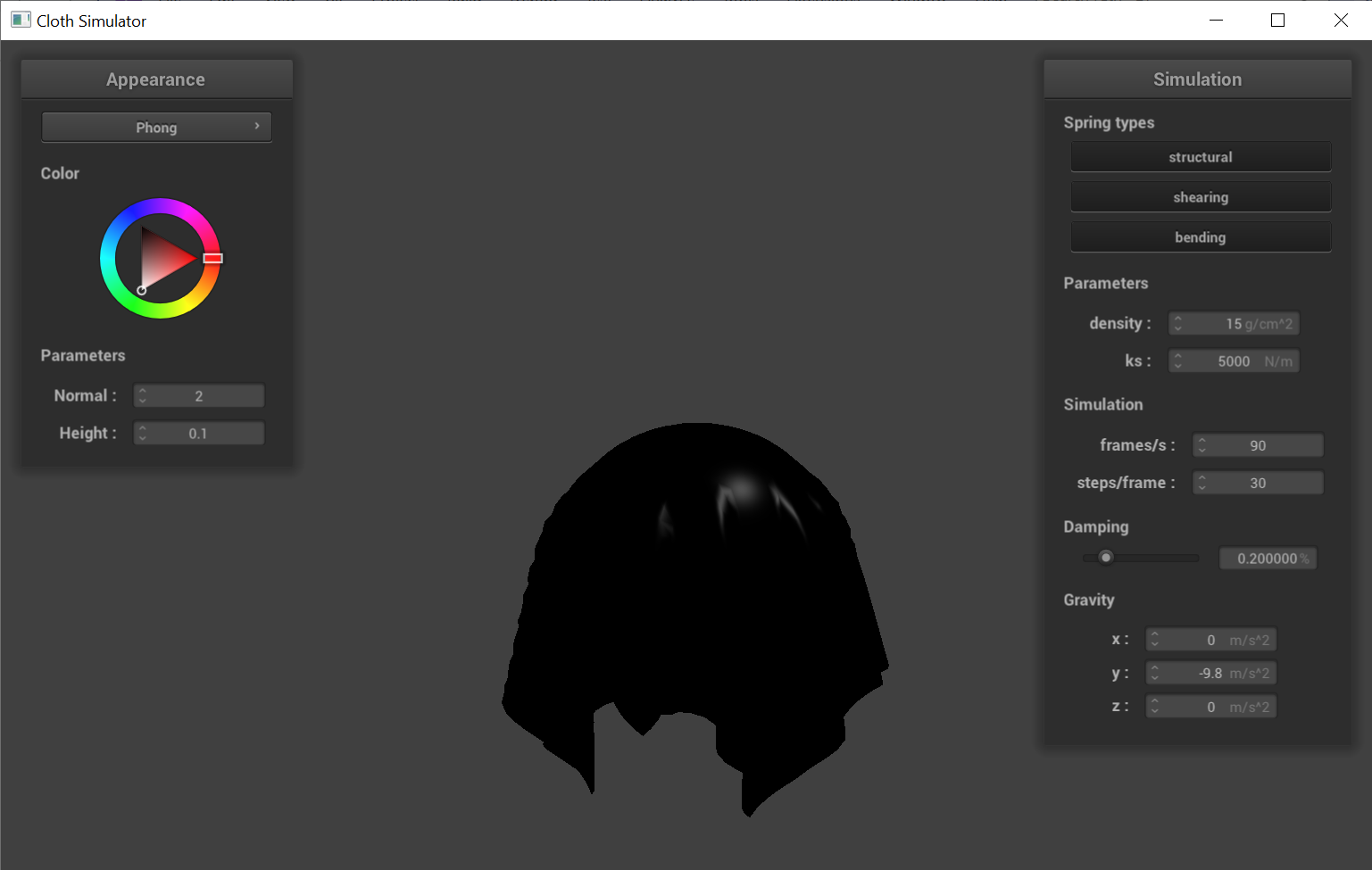
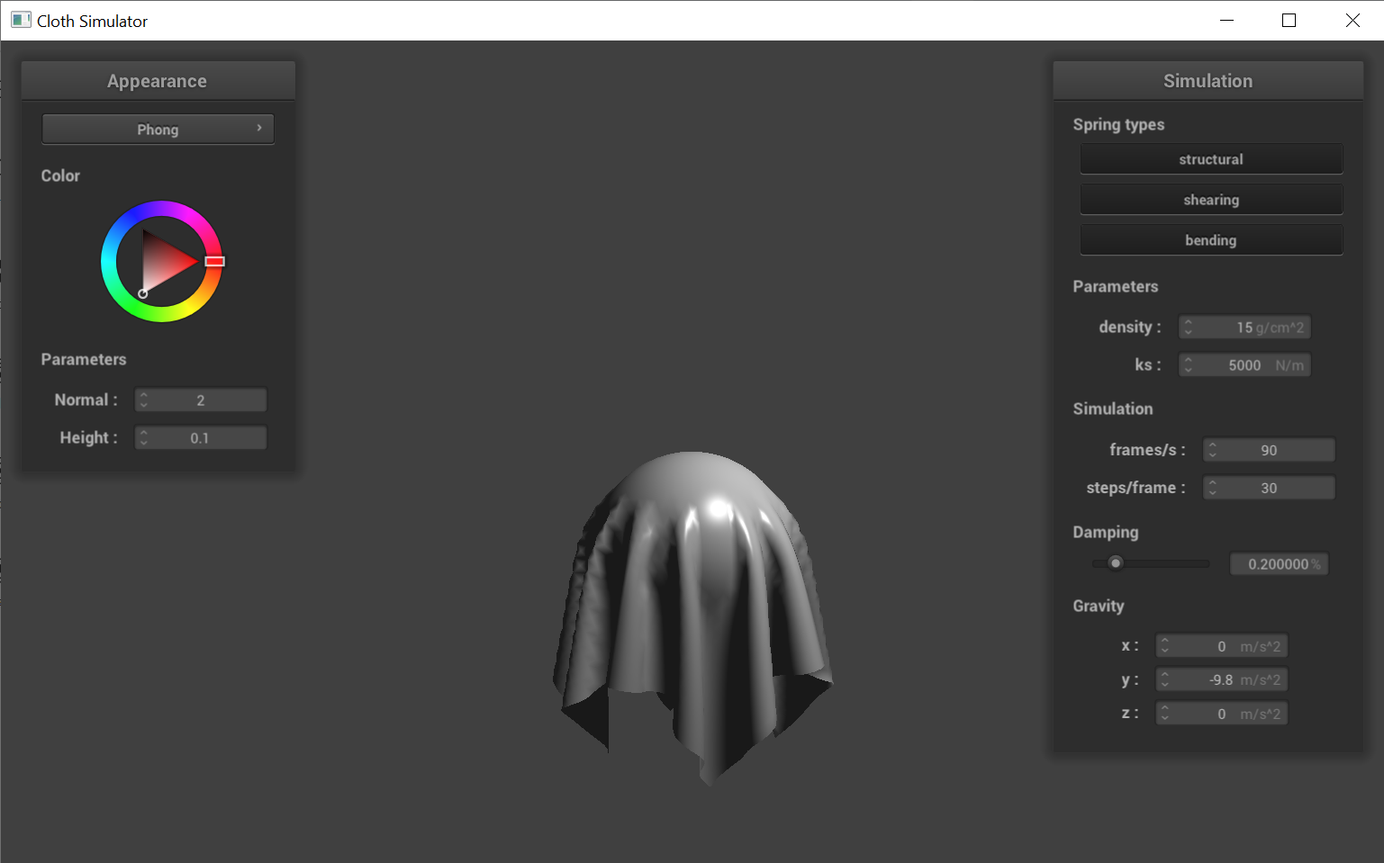
Explain the Blinn-Phong shading model in your own words. Show a screenshot of your Blinn-Phong shader outputting only the ambient component, a screen shot only outputting the diffuse component, a screen shot only outputting the specular component, and one using the entire Blinn-Phong model.
The Blinn-Phong shading model incorporates three componenets of lights: ambient light, diffuse light, and specular light.
p power term for the consine term, which brings out the highlight effects.
|
|
|
|
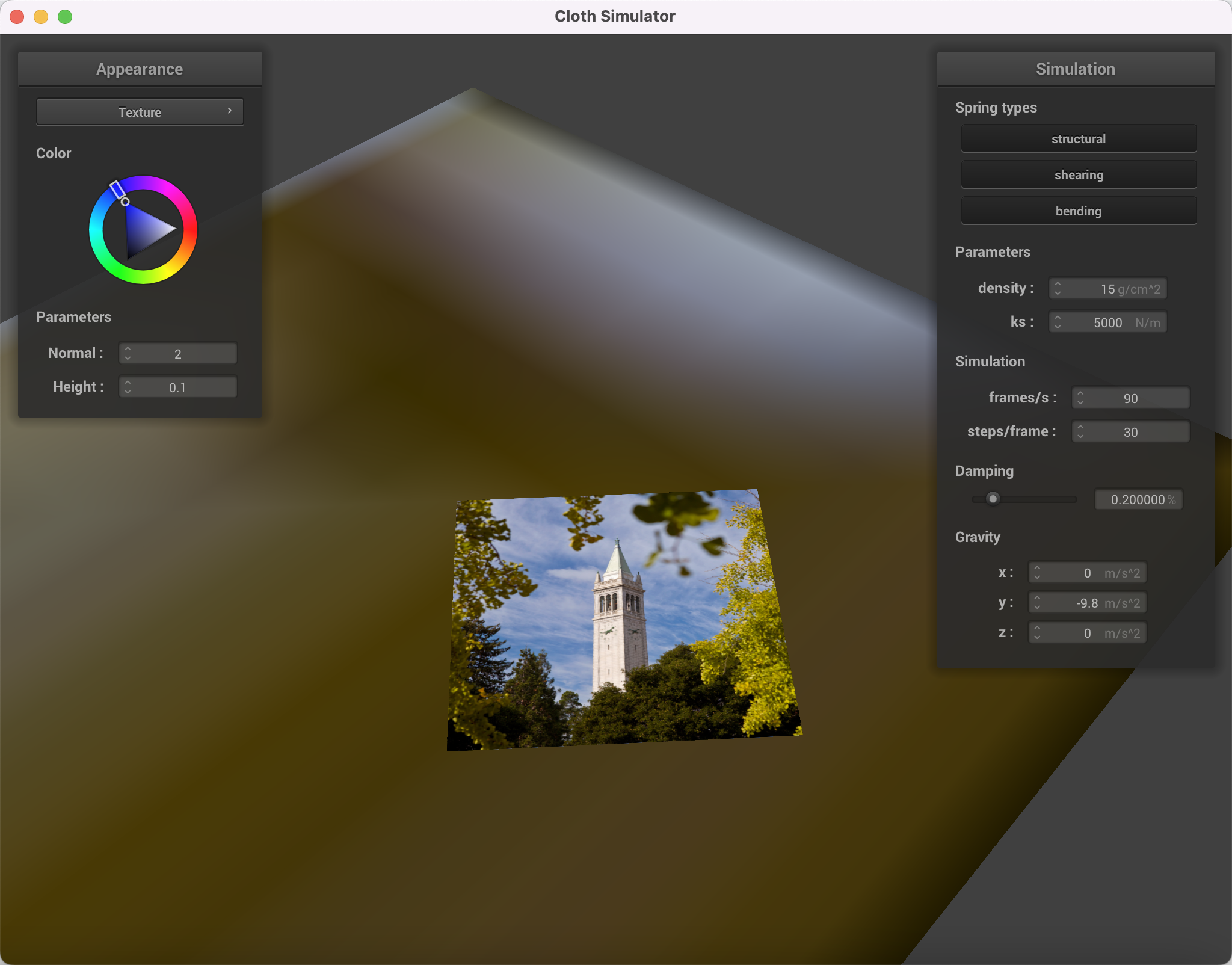
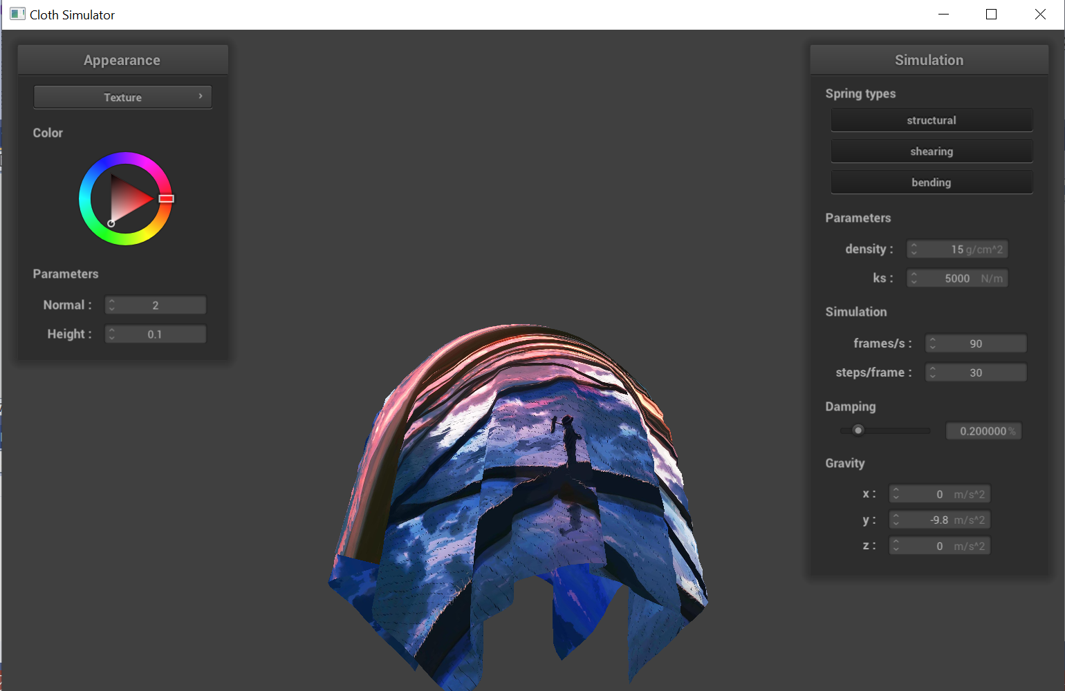
Show a screenshot of your texture mapping shader using your own custom texture by modifying the textures in /textures/.
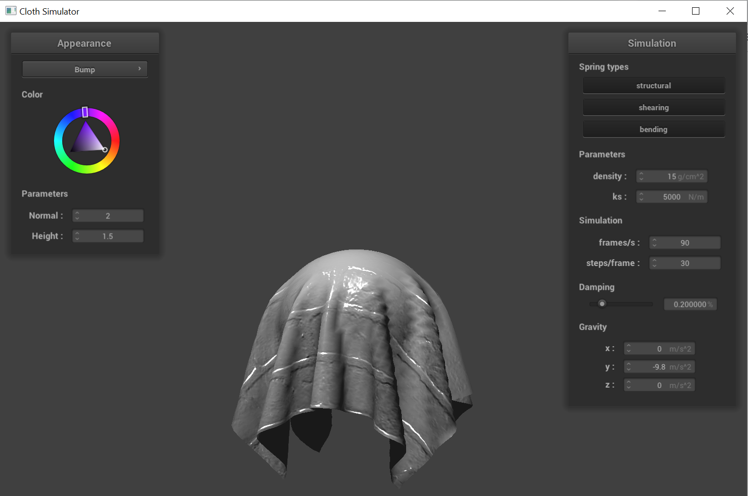
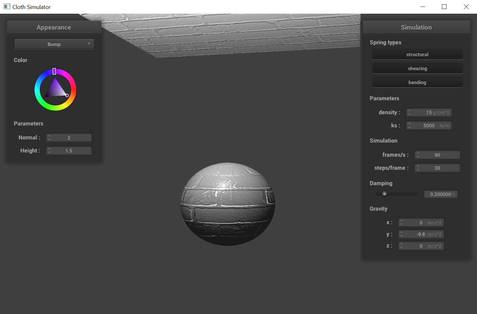
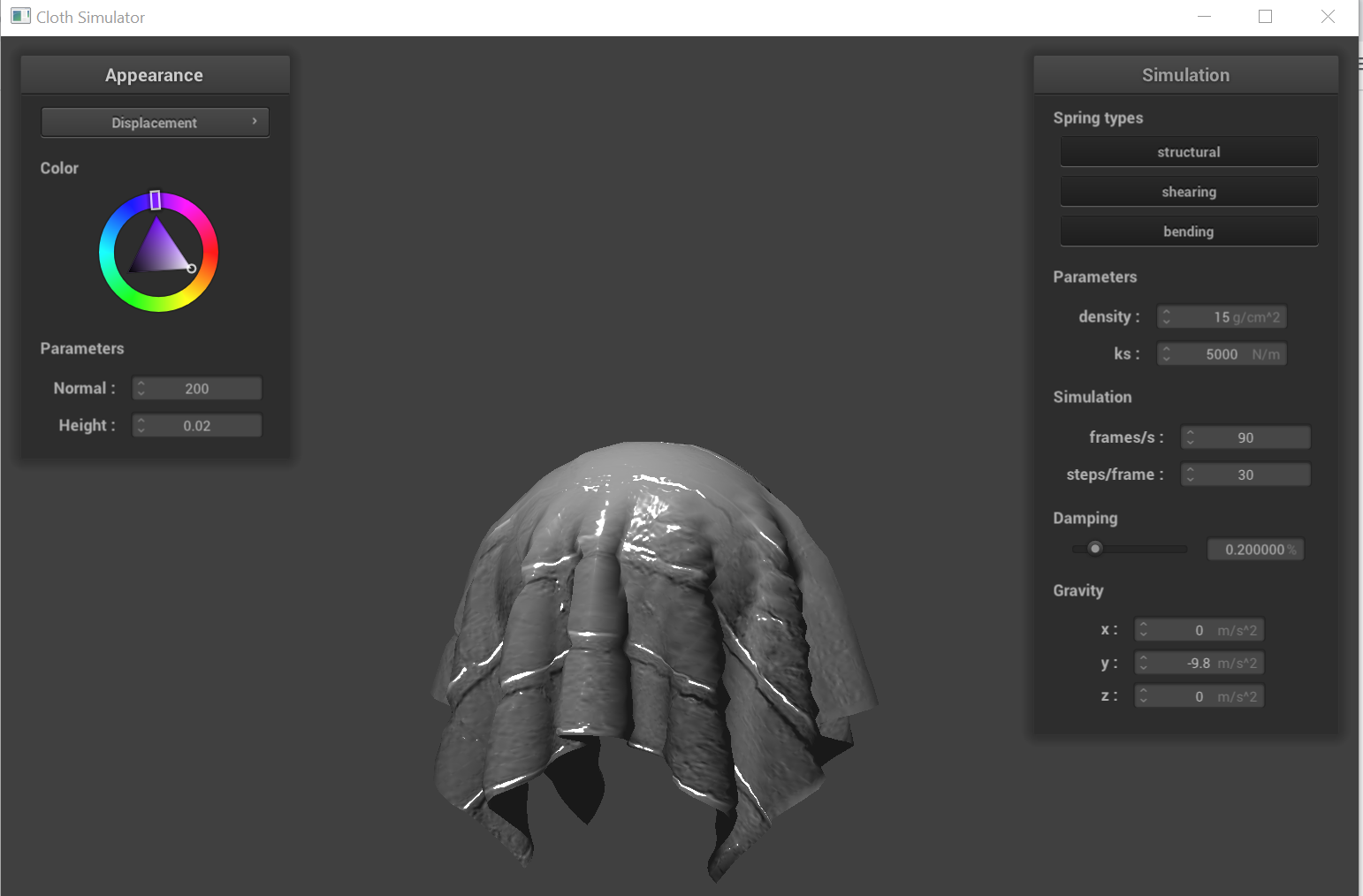
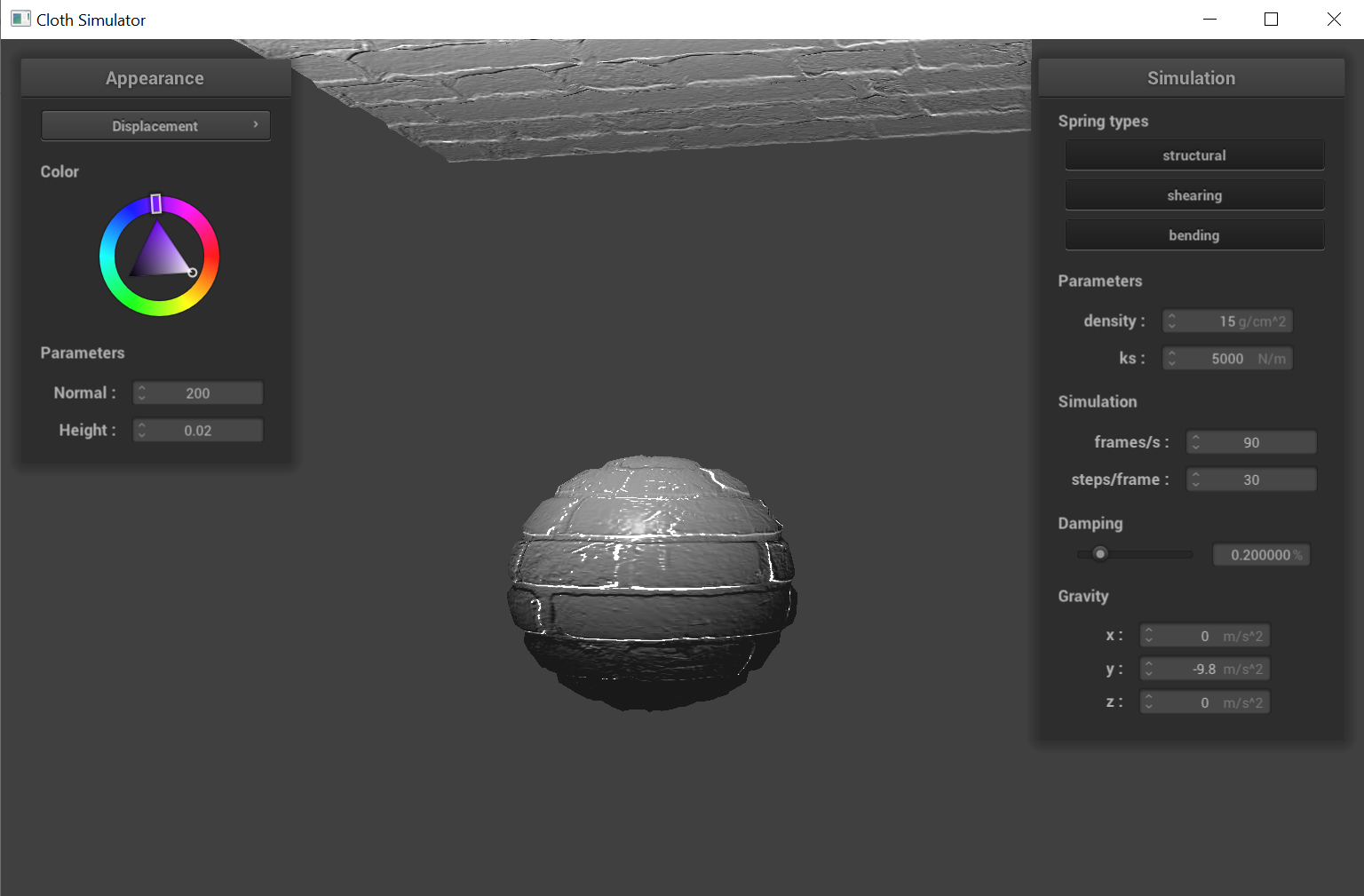
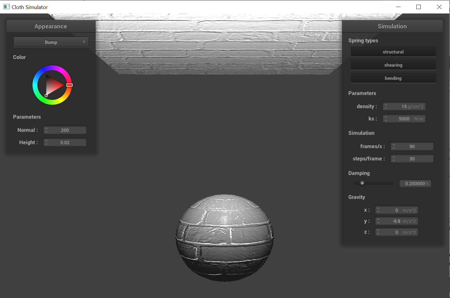
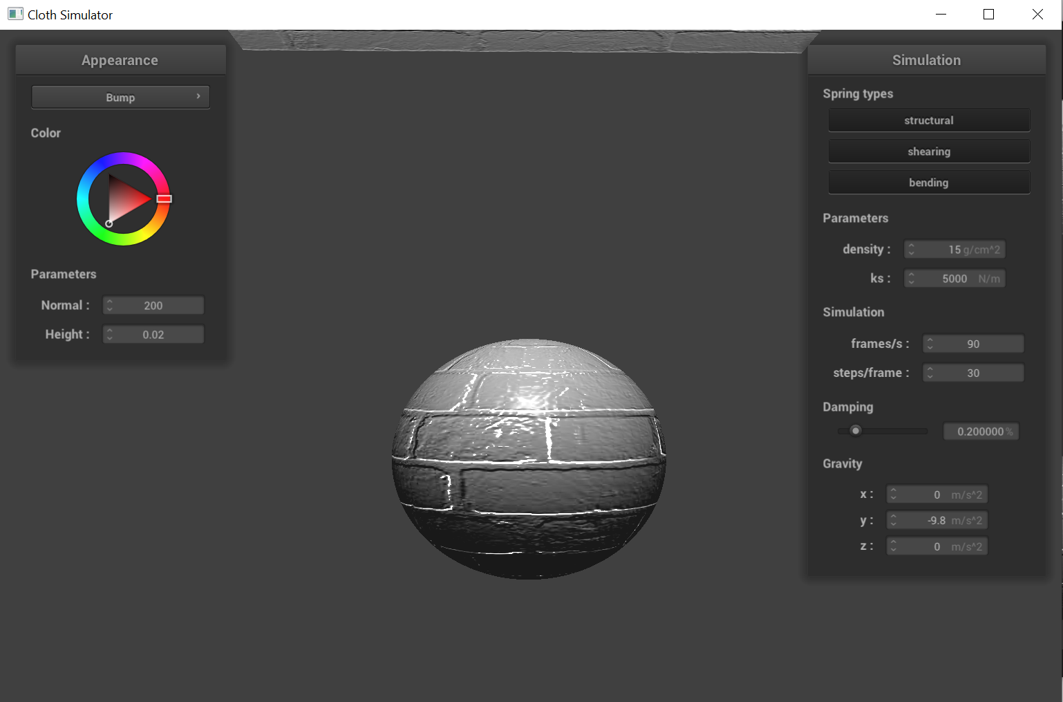
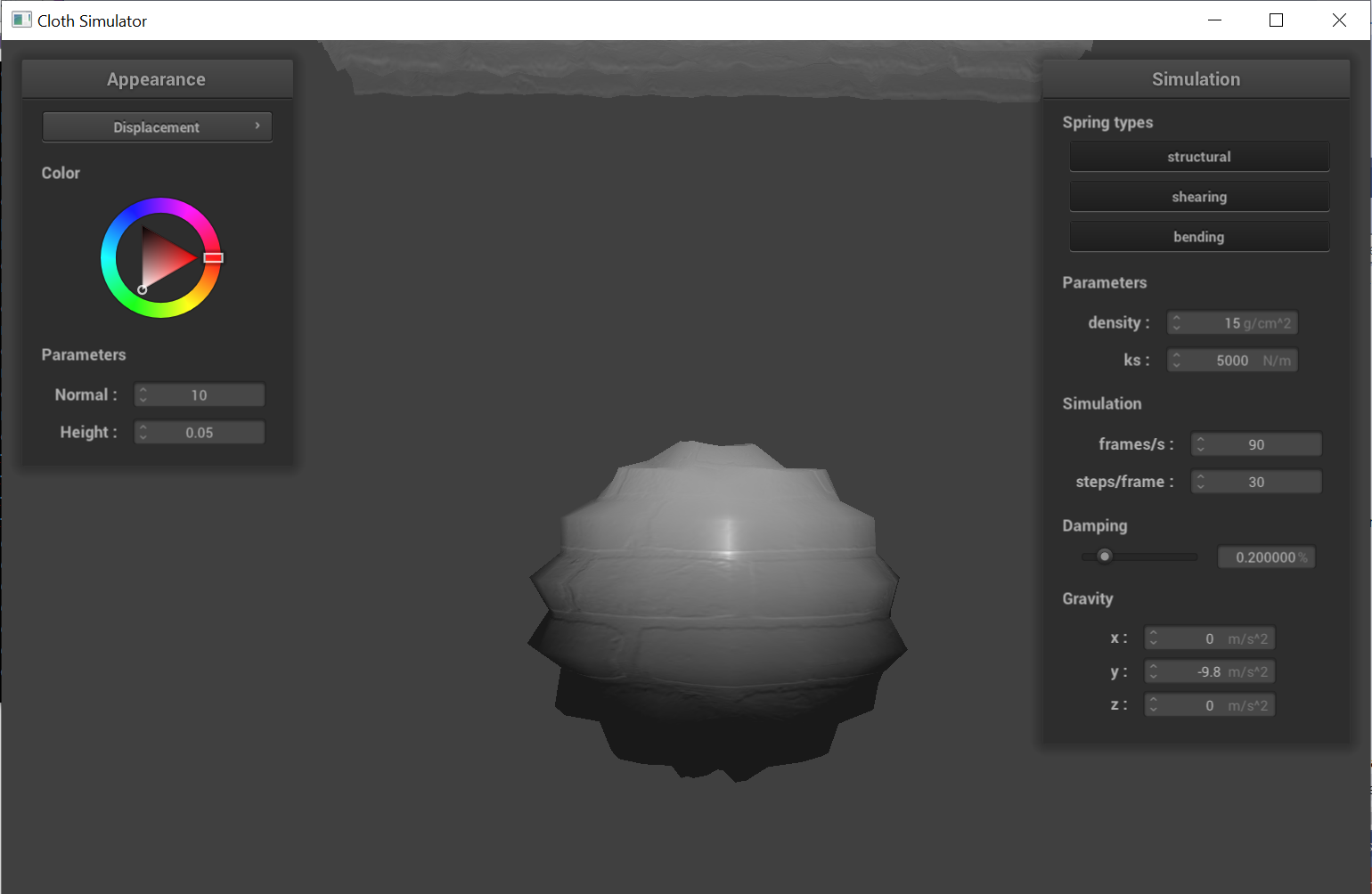
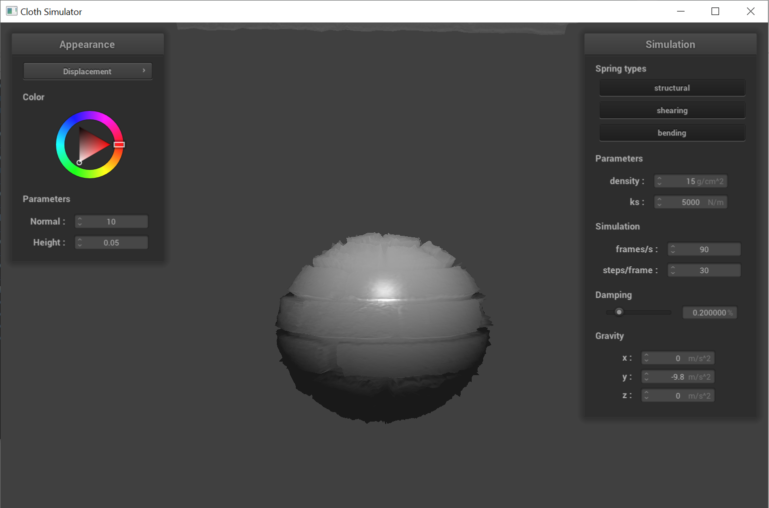
Show a screenshot of bump mapping on the cloth and on the sphere. Show a screenshot of displacement mapping on the sphere. Use the same texture for both renders. You can either provide your own texture or use one of the ones in the textures directory, BUT choose one that's not the defaulttexture_2.png. Compare the two approaches and resulting renders in your own words. Compare how your the two shaders react to the sphere by changing the sphere mesh's coarseness by using-o 16 -a 16and then-o 128 -a 128.
|
|
|
|
|
Looking at the cloth renderings, it is easy to see that both bump mapping and displacement mapping aim to depict texture of the material by incorporating height informations. However, when we take a closer look at the renderings (more obvious on spheres), we see that displacement mapping modifies the actual geometry of the mesh, while bump mapping only manipulates the normal vectors without altering the mesh.
|
|
|
|
|
Comparing the rendering between a high resolution sphere (-o 128 -a 128) and a low resolution sphere (-o 16 -a 16), we observed that the bump mapping method didn't
have much of a difference. But for displacement mapping, we found that the method can take advantage of the increased resolution (along with some
tweaking for normal/height parameters) to encode more accurate and realistic height information into the texture.
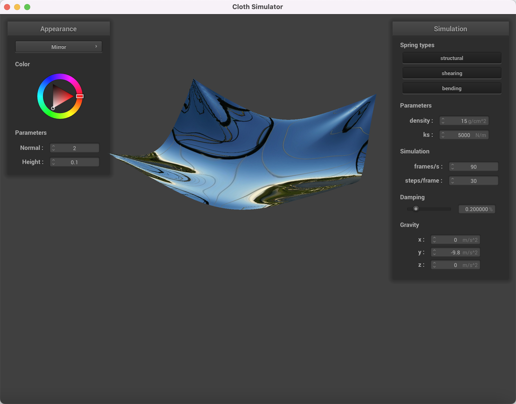
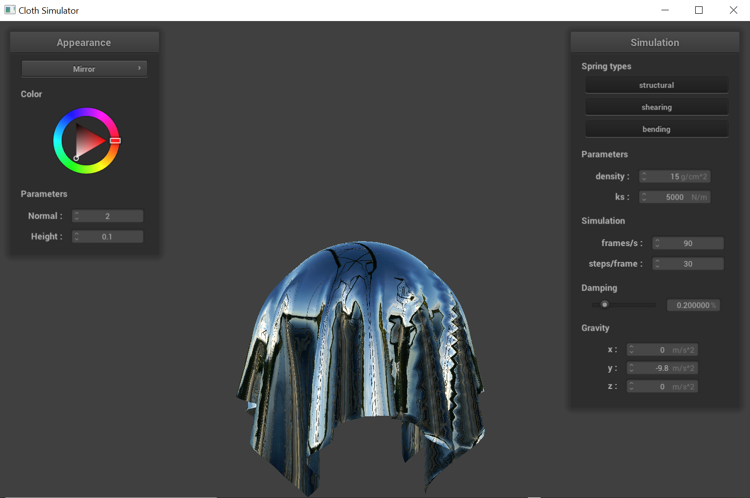
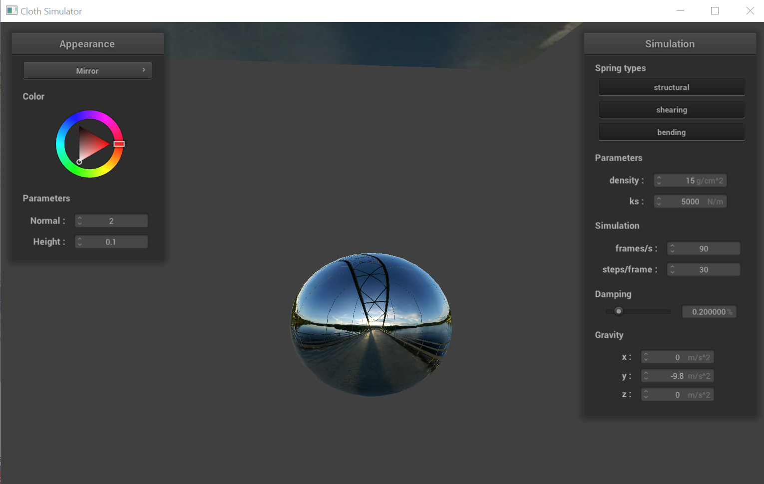
Show a screenshot of your mirror shader on the cloth and on the sphere.
|
|